Memo-Robo


Memo-Robo
Published 2018-04-11T15:44:15+00:00
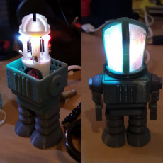
Memo-Robo is a robot with a secret! Part retro-cool robot buddy, part electronic game, Memo-Robo doesn't just light up, he has a built-in memory game!
HOW TO PLAY!
- * When Memo-Robo starts, all the LEDs will light up. Press any button to start!
- * A welcome sequence will flash, then Memo-Robo will show the first light in the sequence.
- * It's your turn! Press the appropriate colour.
- * If you got it right, the lights will all flash once, and Memo Robo will add another to the sequence.
- * Keep going, and see how far you can get before you make a mistake!
- * If you do get it wrong, all the lights will flash a few times, and then will stay lit, waiting for you to press any button and start a new game.
Have fun! :D
WHAT YOU'LL NEED TO BUILD MEMO-ROBO!
You'll need the following:
- * The printed parts, of course
- * Four 5mm LEDs of varying colours
- * Four small pushbutton switches
- * Four 220 ohm resistors
- * Four 10k ohm resistors
- * A NodeMCU development board or similar
- * Wires to hook it all up. Probably a soldering iron, too :)
ASSEMBLING THE PRINTED PARTS!
This is probably self-explanatory, but here's a quick rundown of assembly. We'll start with the head, since that's the complex bit:
- * Take the four push panels, and fit them into the head frame. They'll be a little loose.
- * Take the panel collar and panel retainer, and screw them in from the "neck" to hold the push panels firmly in place.
- * Push the legs into the body so that the snap-fit connectors hold them in place.
- * Take the electronics carriage that you've already completed (see below!), and put it in place in the body. Make sure the USB port is pointing out the hole, or you'll have to take it apart again :P
- * Put the head over the electronics, and fit it snugly into the body. There should be no play in things - the fit should be quite precise.
- * Take the shoulder bolts, put them through the arms, and screw them into the body, which will hold the head assembly in place properly.
BUILDING THE ELECTRONICS!
- * Start by taking one of the LED and button mounts, and fitting the two resistors into it, then the LED and the pushbutton. They should be pretty snug, but if they're loose, a bit of glue won't hurt.
- * Wire up the components on the mount as per the attached image. I recommend constructing it so that there are four wires coming off, each with a female dupont connector - LED control, button signal, 3V and ground.
- * Build all four of the assemblies.
- * Since you need four ground and four 3V connections, it's probably simplest to construct two cables, each with four male and one female connector, and use those to connect the assemblies to a single pin on the board.
- * Push all four mounts into the electronics carriage, and route the wires down to the board.
- * Put the carriage cap on top of the mounts to keep it all nice and solid.
- * Connect each LED and button to the board. Look at the top of the firmware code to work out what should go where, but it's ultimately arbitrary.
- * Upload the firmware! I'll assume you already know how to do this, but if not, there are a ton of guides out there! Just search for NodeMCU Arduino IDE.
DESIGN GOALS
MyMiniFactory announced an Easter design contest in conjunction with Tinkercad, and pushed for entrants to get creative with the idea of a toy within a toy. Rather than just fitting a physical printed toy within the confines of a larger one, I wanted to make the toy do something behaviourally different, and so the concept of incorporating an electronic game was born!
I had a few specific goals in mind:
- * I'd sketched the robot, and really liked the effect of a "head" that tapered to the neck, rather than being straight up-and-down. This presented design difficulties in fitting the push button panels, but I was determined to find a way. This led to the internal thread in the neck block and the two-part collar that retains the panels firmly.
- * Most importantly, the electronics needed to be contained entirely within a single block that could be added or removed easily.
- The electronics carriage had to facilitate wiring up all the components, and hold them neatly in place. This led to the individual LED/button/resistor mounts that could be constructed in isolation, then assembled.
- * The robot had to be robust when assembled, but allow disassembly to add or remove the electronics. This led to the nesting of the neck block inside the body block, with the shoulder bolts holding everything firmly together.
HOW WAS THIS BUILT?
This object was made in Tinkercad. https://www.tinkercad.com/things/3kTknvYuXMb
Feel free to make Memo-Robo do even more! Sound would be an awesome addition! There's also plenty of room in the electronics carriage to add a rechargeable battery and a charging management board.
THE SOURCE CODE (sorry for the text dump!)
/* * Memo-Robo Memory Game v0.1 * Sven Abrahamsson 2018 * * Written as a hidden game in a toy robot - search Memo-Robo on MyMiniFactory for details! * Intended for NodeMCU via Arduino IDE */
// hardware pins corresponding to the LEDs and the buttons// these will obviously be arbitrary depending on your wiringconst int LED_1 = D0; // redconst int LED_2 = D1; // yellowconst int LED_3 = D2; // blueconst int LED_4 = D3; // greenconst int BUTTON_1 = D8; // redconst int BUTTON_2 = D6; // yellowconst int BUTTON_3 = D7; // blueconst int BUTTON_4 = D5; // green
// operational states for the LEDsconst int LED_ON = HIGH;const int LED_OFF = LOW;
// implementation is as a state machine, and these are the states// see nextState() and setState() for transitionsconst int STATE_IDLE = 1; // waiting for the game to startconst int STATE_INTRO = 2; // visual announcement of game startconst int STATE_PRESENTING = 3; // showing the current sequenceconst int STATE_READING = 4; // receiving user input of the sequenceconst int STATE_SUCCESS = 5; // reflect that user was correctconst int STATE_FAILURE = 6; // reflect that user was wrongint currentState = STATE_IDLE;
// speed settings for the game const int DELAY_INTRO = 40;const int DELAY_POST_INTRO = 1000;const int DELAY_PRESENTING_ON = 500;const int DELAY_PRESENTING_OFF = 100;const int DELAY_SUCCESS = 500;const int DELAY_FAILURE = 200;const int DELAY_BUTTON_SUCCESS = 500;const int DELAY_DEBOUNCE = 400;
// main data structure for the gameint sequence[200];int sequenceLength = 0;
void setup() { pinMode(LED_1, OUTPUT); pinMode(LED_2, OUTPUT); pinMode(LED_3, OUTPUT); pinMode(LED_4, OUTPUT); pinMode(BUTTON_1, INPUT_PULLUP); pinMode(BUTTON_2, INPUT_PULLUP); pinMode(BUTTON_3, INPUT_PULLUP); pinMode(BUTTON_4, INPUT_PULLUP); setState(STATE_IDLE);}
void loop() { switch (currentState) { case STATE_IDLE: doIdle(); break; case STATE_INTRO: doIntro(); break; case STATE_PRESENTING: doPresenting(); break; case STATE_READING: doReading(); break; case STATE_SUCCESS: doSuccess(); break; case STATE_FAILURE: doFailure(); break; }}
void doIdle() { // waiting for the game to begin! // just turn on the LEDs and block, waiting for a button press setAllLEDs(LED_ON); waitForButton(); nextState();}
void doIntro() { // show an intro to indicate the game is beginning // basically, we flash some lights. setAllLEDs(LED_OFF); for (int j = 0; j < 2; j++) { for (int i = 1; i <= 4; i++) { delay(DELAY_INTRO); setLED(i, LED_ON); } for (int i = 1; i <= 4; i++) { delay(DELAY_INTRO); setLED(i, LED_OFF); } } delay(DELAY_POST_INTRO);
// initialise the game state clearSequence(); addToSequence(); nextState();}
void doPresenting() { // game is running - display the current sequence to the player for (int i = 0; i < getSequenceLength(); i++) { setAllLEDs(LED_OFF); setLED(getSequenceElement(i), LED_ON); delay(DELAY_PRESENTING_ON); setAllLEDs(LED_OFF); delay(DELAY_PRESENTING_OFF); } nextState();}
void doReading() { // game is running - wait for the player to enter the sequence setAllLEDs(LED_OFF); for (int index = 0; index < getSequenceLength(); index++) { int buttonNum = waitForButton(); if (buttonNum == getSequenceElement(index)) { // correct button! show the LED for the button pressed. setLED(buttonNum, LED_ON); delay(DELAY_BUTTON_SUCCESS); setAllLEDs(LED_OFF); } else { // wrong button - game over, man, game over! setState(STATE_FAILURE); return; } }
// sequence was completed successfully nextState();}
int waitForButton() { // blocks and waits for user to press a button // returns button number. Note all the calls to // ESP.wdtFeed(). This is the keep the system watchdog // at bay while the call loops indefinitely and waits // for input. Without this, the board will reset!
static long lastPress = 0; // debounce controller
// first wait for no button to be pressed, and // for the debounce period to have passed. while ( (digitalRead(BUTTON_1) == HIGH) || (digitalRead(BUTTON_2) == HIGH) || (digitalRead(BUTTON_3) == HIGH) || (digitalRead(BUTTON_4) == HIGH) || millis() - lastPress < DELAY_DEBOUNCE) { ESP.wdtFeed(); }
// now wait until a button is pressed int pressed = 0; while(pressed == 0) { ESP.wdtFeed(); for (int index = 1; index < 5; index++) { if (digitalRead(getButton(index)) == HIGH) { pressed = index; } } } lastPress = millis(); // recorded for debouncing return pressed;}
void doSuccess() { // sequence has been input entirely and correctly!
// flash some lights setAllLEDs(LED_OFF); delay(DELAY_SUCCESS); setAllLEDs(LED_ON); delay(DELAY_SUCCESS); setAllLEDs(LED_OFF); delay(DELAY_SUCCESS);
// add an other element to the sequence addToSequence(); nextState();}
void doFailure() { // indicate game over! for (int i=0; i < 5; i++) { setAllLEDs(LED_ON); delay(DELAY_FAILURE); setAllLEDs(LED_OFF); delay(DELAY_FAILURE); }
// this will take us back to idle nextState();}
void clearSequence() { // reset the game data sequenceLength = 0;}
void addToSequence() { // add a single random element to the game data sequenceLength++; randomSeed(millis()); sequence[sequenceLength -1] = random(1,5);}
int getSequenceLength() { // get the current game sequence length return sequenceLength;}
int getSequenceElement(int index) { // index is a zero-based reference into the sequence if (index >= 0 && index < sequenceLength) { return sequence[index]; } else { return 0; }}
void nextState() { // implements default state transitions. see also setState() switch (currentState) { case STATE_IDLE: currentState = STATE_INTRO; break; case STATE_INTRO: currentState = STATE_PRESENTING; break; case STATE_PRESENTING: currentState = STATE_READING; break; case STATE_READING: // default transition - use setState to mark failure instead currentState = STATE_SUCCESS; break; case STATE_SUCCESS: currentState = STATE_PRESENTING; break; case STATE_FAILURE: currentState = STATE_IDLE; break; }}
void setState(int state) { // used to override the default state transitions in nextState() currentState = state;}
void setAllLEDs(int state) { // sets the state of all LEDs - pass LED_ON or LED_OFF for (int i = 1; i <= 4; i++) { setLED(i, state); }}
void setLED(int num, int state) { // sets the state of a single LED - pass LED_ON or LED_OFF digitalWrite(getLED(num), state);}
int getLED(int num) { // map index to pin constants switch(num) { case 1: return LED_1; case 2: return LED_2; case 3: return LED_3; case 4: return LED_4; }}
int getButton(int num) { // map index to pin constants switch(num) { case 1: return BUTTON_1; case 2: return BUTTON_2; case 3: return BUTTON_3; case 4: return BUTTON_4; }}


Designed for easy printing! The only part that might be a little tricky is the set of four push panels, which might need a brim in order to stay stuck down to the bed. I managed to print them standing up, but I did have my fingers crossed the whole time! Everything else should be pretty simple!
| Date published | 11/04/2018 |
| Tecnología | FDM |

Printed it on 50% :-) printed on a Renkforce RF100 V2