Neo Geo Flash Masta Cart Shell
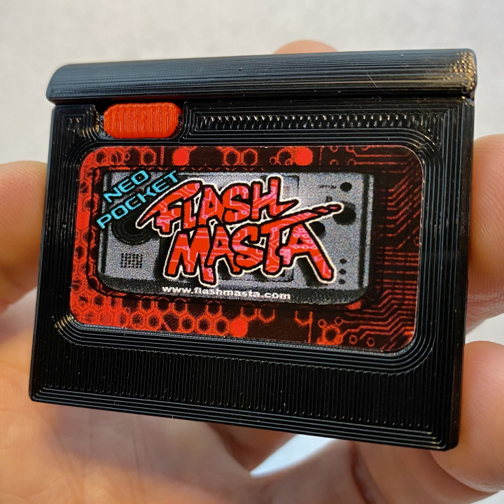


Neo Geo Flash Masta Cart Shell
Published 2021-04-08T11:07:30+00:00
Quick video showing an IMPORTANT little spot to file so the snap works right. WATCH FIRST https://youtu.be/C-RvA9iIdaM
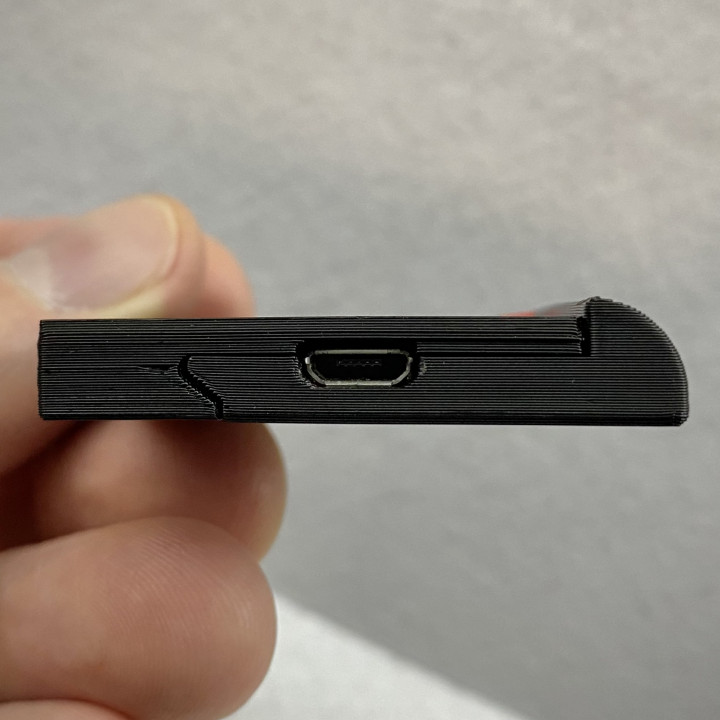
The tl;dr is that you need to file a tiny spot on the snap button; if you close the shell without doing that it will be difficult to open.
--------------------
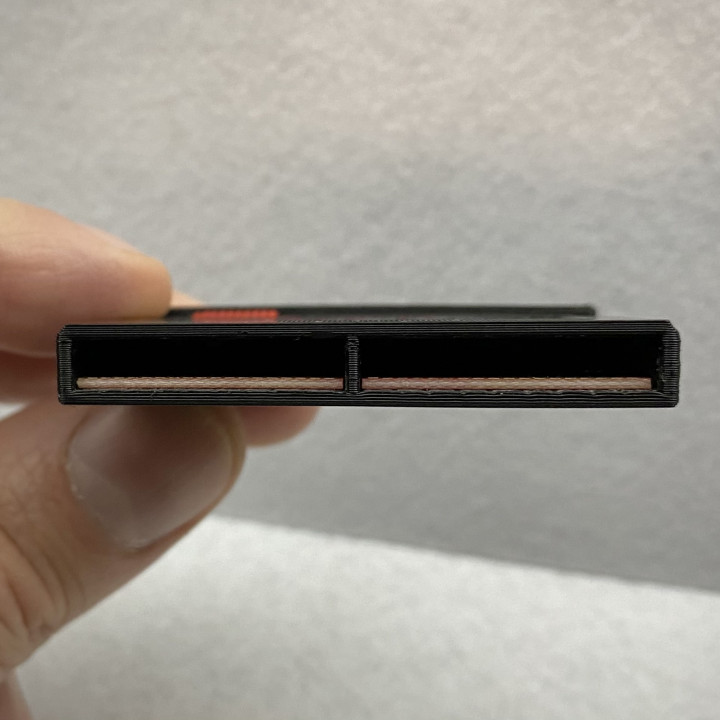
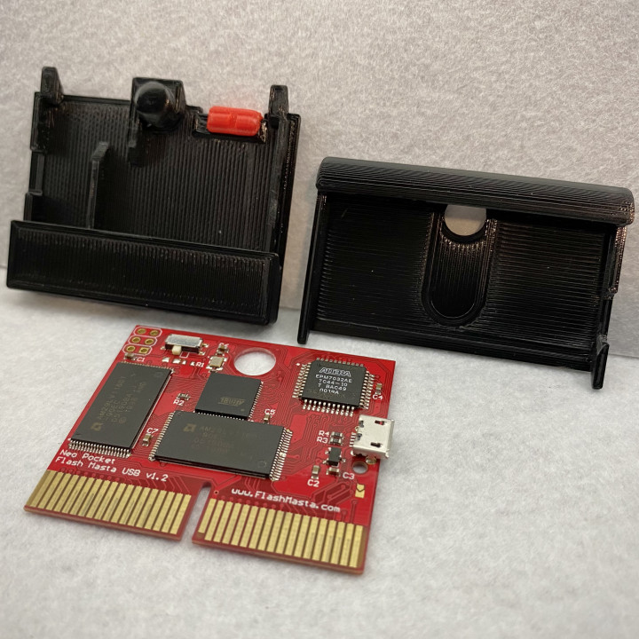
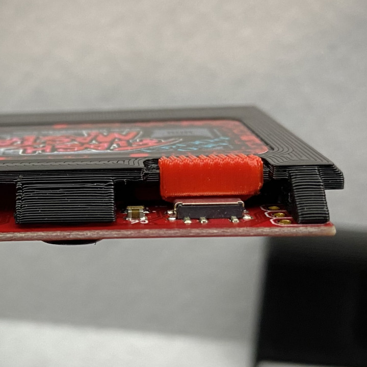
The Neo Geo Pocket has a picky cartridge connector. It NEEDS the cartridge shell to enclose the connector on the device pinning the cartride pins to the connector. For other systems, like the WonderSwan, the cartridge only needs a little spacer on the back and it works fine. Not the Neo Geo Pocket. It also is picky about the AMOUNT of force with which the cartridge is pressed against the connector. So this shell needs to be printed accurately. I use .2mm layer height and that INCLUDES THE FIRST LAYER. I have found the connection has a high failure rate if .3mm initial layer height is used becuse that slightly alters the connector space available in the shell. Also, it's a good idea to prioritize strength at the cartridge connector as there is outward force from the connector there. I print with no fan, slower speeds, and decent temps for this reason.
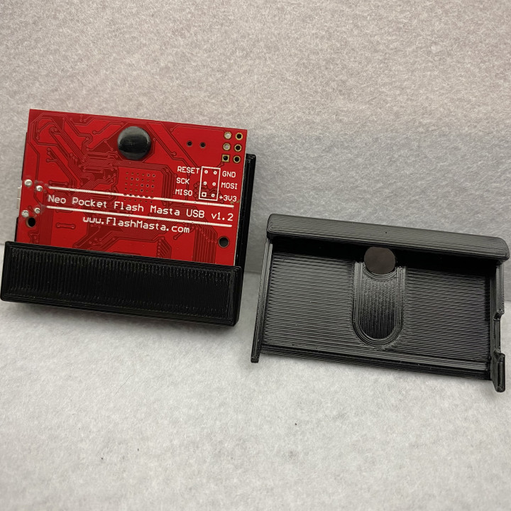
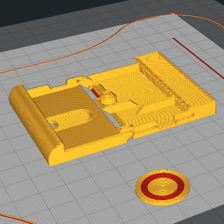
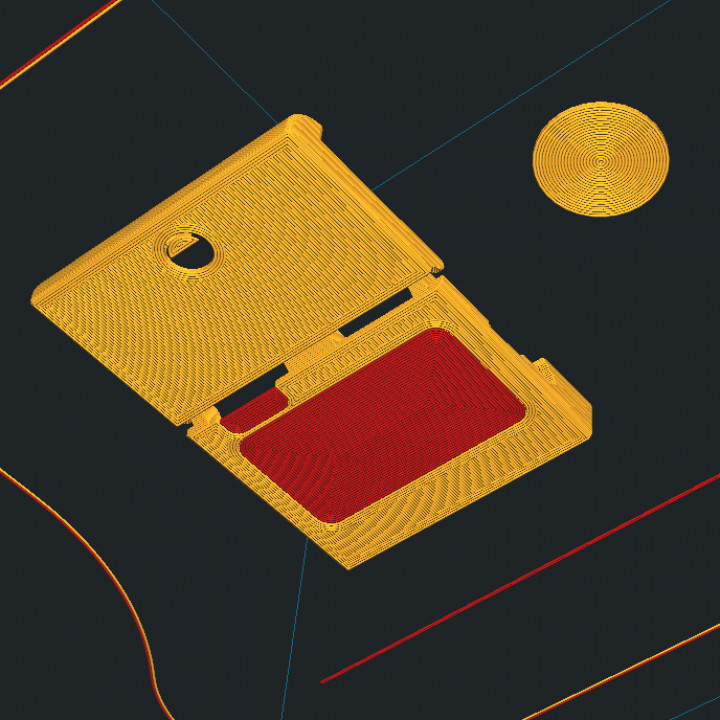
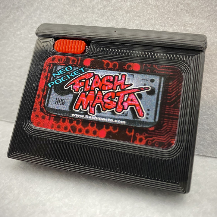
I will include 2 versions of the front half of the shell, 1 with the decal space and 1 without (flush/flat front).
I designed this shell from the starting point of having as much of the surface(s) printed on the bed as possible. This makes texture options kind of easy. Especially since they are printed in PETG and post processing like painting is a bit limited as far as I know.
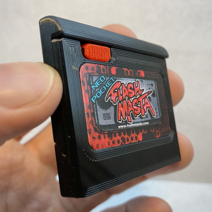
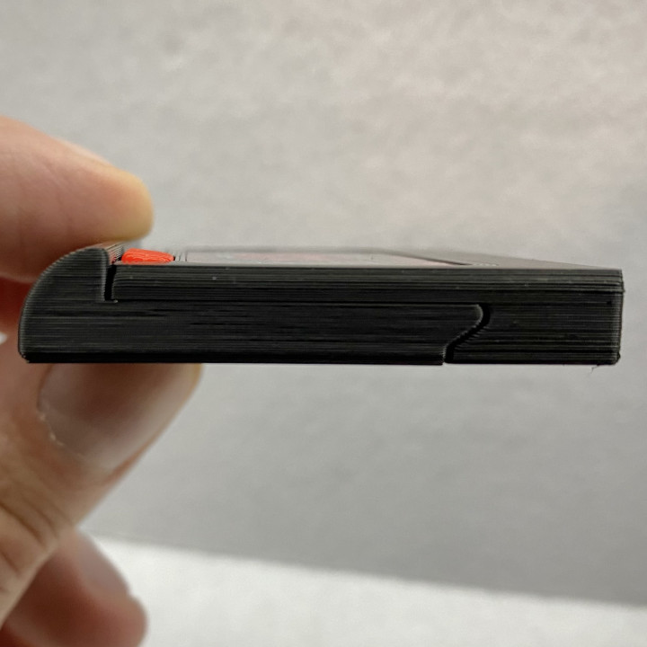
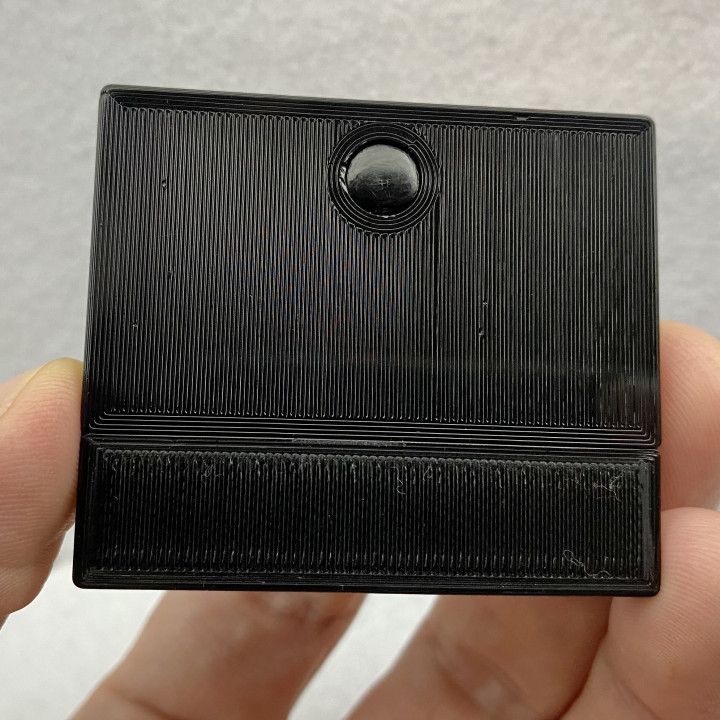
Oh right, I have only printed these in PETG. One other design feature I wanted from the start was to be able print it completely, so no need for screws or other hardware. PETG helped with that I think. The SLIGHT flexibility of PETG makes the rear button work. Although, I haven't tried in PLA, and my idea about PETG beign necessary for this could be wrong. To snap and unsnap the shell you press the rear button with your thumb while 2 other fingers are each on the front top corners. You can see me unsnap one here at the very beginning of this video https://www.youtube.com/watch?v=0_MvwMafc9o . I have modeled the button to be barely too tall to afford material so you can file/polish the top of it, and dial in the snap a bit as needed.
I have recently recalibrated my printers esteps and have tested this model before uploading this initial iteration. At the moment I feel the snap is a little too loose. It works completely fine, and noone would likely notice any difference, but I plan to tweak the model in the next few days to tighten it back up to the dimensions I had been seeing with my previously incorrect esteps. This prioritizes a strong sturdy feel over ease of snapping and unsnapping since it isn't likely needed to be snapped and unsnapped much anyway.
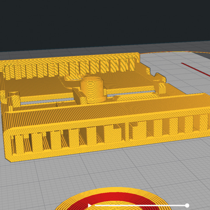
I use supports to ensure dimensional accuracy of the overhangs since they are funcionally important. For example, the overhang on the Back part is a functional part of the closing mechanism. The triangular parts of the Front need to press against there when closed for a good fit, and of course the cartridge connection point needs to be spot on. I clean up the supports of the cartridge connctor and then do light filing to debur it and, it probably makes no difference here, I finilize things by hitting it all with a little heat.
I print the decal version using 2 materials, PETG for the shell and PLA for the button support and decal spacer. I THINK using PLA spacers/supports this way gives me a better surface in that area than it would be using supports. Supports would be fine for the button area, but may require just a bit of smoothing out there with a file or similar. I haven't tried supports for the decal inset. It is only .2mm inset, so I had thought the normal support defects would be too much, but good support settings (roof etc) might do just fine.
For the Button, I've included a little support piece as part of the model. I found it much easier to just clip/cut that off instead of trying to get good slicer supports. I print the button standing tall with the flatter side to the bed. In cleaning up I just round the edge a bit with a file to match the other side. I tried different ways of printing the tiny thing and the flatter side has helped a lot.
LET ME KNOW if I've messed anything up or anything else and I'll see what I can do. I'll update this model when I can and will especially if there are any issues with it.
- 13April2021: Working on those few initial sizing tweaks, and working out better print settings. I should get those things uploaded soon.
- 16April2021: Added updated files, video, and settings (settings in the Printing tips section). I have tweaked the models to tighten things up a bit as well as make relevant Z dimensions more accurate so slicers have less guesswork to do. I've also done a lot of printing to dial in those settings.


Printed in PETG with PLA decal spacer and button support. If I print the Back with the Front in the same print I will set the Back model to NOT iron at all. I pretty much just iron the highest layer, which is the button top, to help smooth that surface to make polishing it a little easier.
-QUALITY-
Layer Height: .2
Initial Layer Height: .2
Line Width: .4
Initial Layer Line Width: 115
-SHELL-
Wall Line Count: 3
Outer Wall Wipe Distance: .2mm
Top Layers: 1
Bottom Layers: 2
Top/Bottom Pattern: Lines
Bottom Pattern Initial Layer: Lines
Top/Bottom Line Directions: [180,45,135,45,180,90,180,135,45,135,90,45,135,45,135,45,135,45,135,45,135,45,135,45,135,45,135,45,135,45,135,45,135,45,135,45]
Optimize Wall Printing Order: Yes
Fill Gaps Between Walls: Everywhere
Print Thin Walls: Yes
Z Seam Corner Preference: User Specified
Z Seam Position: Front Left
Seam Corner Preference: Smart Hiding
Enable Ironing: Yes
Iron Only Highest Layer: Yes
Ironing Pattern: Concentric
Ironing Flow: 2.5%
Ironing Speed: 15mm/s
Skin Overlap Percentage: 5%
-INFILL-
Infill Density: 100%
Infill Pattern: Lines
Infill Layer Thickness: .2mm
-MATERIAL-
Printing Temperature: 235c
Printing Temperature Initial Layer: 245c
Build Plate Temperature: 75c
Support Flow 105%
Initial Layer Flow 130%
-SPEED-
Print Speed: 40mm/s
Infill Speed: 40mm/s
Wall Speed: 10/mm/s
Outer Wall Speed: 10mm/s
Innter Wall Speed: 10mm/s
Top Surface Skin Speed: 8mm/s
Top/Bottom Speed: 40mm/s
Support Speed: 15mm/s
Prime Tower Speed: 20mm/s
Travel Speed: 300mm/s
Initial Layer Speed: 25mm/s
initial Layet Travel Speed: 100mm/s
Skirt/Brim Speed: 25mm/s
Number of Slower Layers: 1
-TRAVEL-
Enable Retraction: Yes
Retraction Distance: 2mm
Retraction Speed: 25mm/s
Retraction Prime Speed: 65mm/s
Retraction Extra Prime Amount: .096
Retraction Minimum Travel: .8mm
Layer Start X: 0
Layer Start Y: 120
Z Hop After Extruder Switch Height: .2mm
-COOLING-
No
-SUPPORT-
Generate Support: Yes
Support Structure: Normal
Support Placement: Everywhere
Support Overhang Angle: 65
Support Patter: Zig Zag
Support Wall Line Count: 0
Support Density: 20%
Support Infill Line Directions: [180]
-BUILD PLATE ADHESION-
Build Plate Adhesion type: Skirt
Skirt Line Count: 1
Skirt Distance: 30
-DUAL EXTRUSION-
Enable Prime Tower: Yes
Prime Tower Size: 20mm
Prime Tower Minimum Volume: 20
Prime Tower X Position: 120mm
Prime Tower Y Position: 31mm
Wipe Iniactive Nozzle on Prime Tower: Yes
Nozzle Switch Extra Prime Amount: .064
| Date published | 08/04/2021 |